Post-quake
status of the
Kashiwazaki-Kariwa
Nuclear Power Station
(Report #11)
- Update on the status
of inspection and
restoration work through
to November 8
-
The Report #11
follows on from Report
#10 in summarizing the
post-quake status of the
Kashiwazaki-Kariwa
Nuclear Power Station
and giving the overview
of the initiatives,
trends and other details
involving Tokyo Electric
Power Company (TEPCO)
and other relevant
organizations.
1. Earthquake
response evaluation of
reactor
buildings
TEPCO briefed on the
earthquake response
evaluation of the power
station's reactor
buildings at the 6th
meeting of the
Structural Working Group
under the Anti-Quake
Structural Design
Subcommittee, Nuclear
Safety Committee, METI
Advisory Committee for
Natural Resources and
Energy, convened on
October 23.
This assessment used
seismic observation
records to simulate the
earthquake response of
the reactor buildings
for analysis, and
calculated their maximum
response shear strain
accordingly, to compare
the figure against the
benchmark figure for the
development of shear
cracks (Allowable Stress
Design, Architectural
Institute of Japan
Standards for Structural
Calculation of Steel
Reinforced Concrete
Structures and Brief
Commentary, 1999).
(1)
Simulation
reproducing the
earthquake response
of reactor
buildings
When the following
conditions are taken
into account, the
simulation of reactor
buildings' earthquake
response produced
results that match
the seismic
observation records
relatively well.
i.
Young's modulus
for concrete
ii. Wall
setting for
rigidity
evaluation (Wall
that meets the
criteria
stipulated in
Article 19 of the
AIJ Standards for
structural
Calculation of
Steel Reinforced
Concrete
Structures and
Brief Commentary
[Allowable
Stress
Design],
1999)
iii. Ground
foundation around
the reactor
buildings
(2) Maximum
response shear strain
of the reactor
buildings
The conditions of
the simulation were
applied to calculate
the maximum response
shear strain of the
reactor buildings,
and the results for
all the reactor
buildings were below
the benchmark figure
for the development
of shear cracks,
indicating that the
structures fell
within the designed
scope of resilience.
WG members did not
present any major
arguments that deny
the finding.
(3) Summary of
TEPCO's assessment
results and immediate
initiatives
i. The
analysis that took
actual earthquake
conditions into
account was able
to reproduce the
seismic
observation
records relatively
well. (Figures 1
and 2 show the
example of Unit 2,
which suffered
seismic motions
that exceeded the
level assumed at
the time of plant
designing most
drastically.)
ii. The maximum
response shear
strain, obtained
in the analysis,
indicates that the
reactor buildings
fall within the
designed scope of
resilience.
(Figure 3 shows
the example of
Unit 2.)
iii. The
results are to be
compared against
the outcome of
crack checks and
other inspections
currently underway
to confirm the
buildings'
integrity.
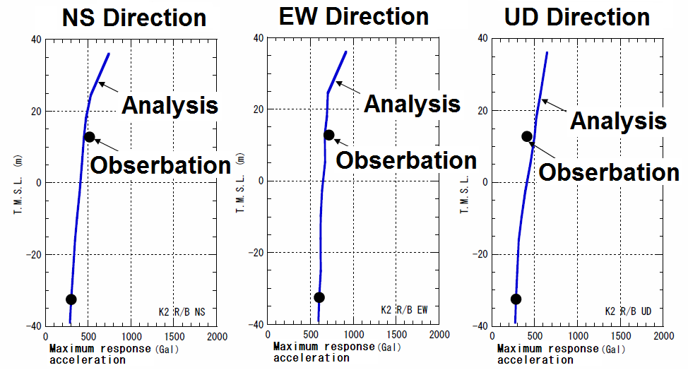
Fig. 1 Maximum response
Acceleration (Unit
2)
Source: Courtesy of the
TEPCO
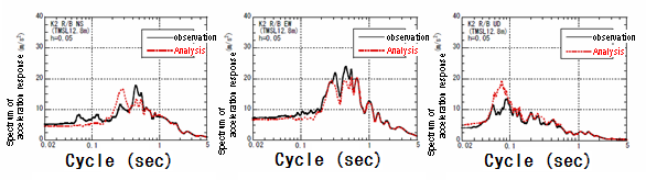
Fig. 2 Comparison of
floor response spectrum
(on a mid floor) (Unit
2)
Source: Courtesy of the
TEPCO
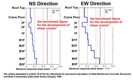
Fig. 3 Maximum response
shear strain of the
reactor building (Unit
2)
Source: Courtesy of the
TEPCO
2.Status of main
inspection and
restoration work
Detailed inspection
and restoration work on
equipment, etc. is
systematically being
carried out at the
Kashiwazaki-Kariwa
Nuclear Power Station at
present. TEPCO releases
inspection findings as
they become available.
See
the attachment for a
list of performed and
planned inspection /
restoration work.
According to the
reference materials
released by TEPCO thus
far, no serious plant
damage has been
identified in the course
of the inspection /
restoration work. The
following describes the
results of some of the
inspections that have
caught the attention of
JANTI:
(1)-1
Water leakage at Unit
7
TEPCO completed
filling the Unit 7
reactor with water on
October 8, 2007.
Although some seepage
has subsequently been
identified as
described below, the
amount of water
involved is minute
with no radiation
effects to the
outside
environment.
a.
Detection of drain
water from the
reactor well
liners
TEPCO found
some water inside
a level gauge
connected to the
well liner, and
conducted trend
monitoring as well
as analysis of the
water itself, to
detect a minute
amount of
radioactive
material (antimony
124).
It is believed
that some of the
water used for
filling the upper
reactor flowed
into the level
gauge via the
liner. (See the
diagram
below.)
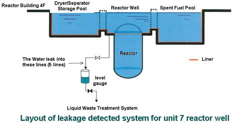
Source: Courtesy of the
TEPCO
This
leakage did not
cause any
radioactive impact
on the external
environment.
The liner is
currently being
inspected, with
minor damage that
could lead to
leakage identified
in two locations.
The damaged
sections are to be
temporarily
repaired before an
in-core inspection
is conducted.
b. Water
leakage in
radiologically
controlled areas
on the 2nd floor
of the reactor
building
TEPCO
identified water
seepage from minor
wall cracks and
puddles of water
on the floor in
radiologically
controlled areas
on the 2nd floor
of the reactor
building. Analysis
of the leaked
water detected a
minute amount of
radioactive
materials
(cobalt-60 and
cesium-137).
The amount of
water leaked
totaled 6.5 liters
containing
radioactivity of
250Bq, which is
equivalent to
radioactivity
found in around
30cc of radon spa
water.
The leakage
stayed within the
radiologically
controlled area,
thereby posing no
radiation impact
on the external
environment.
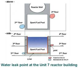
Since the
amount of leakage
drops when the
water level of the
reactor well goes
down, TEPCO
suspects that the
leakage came from
the well. An
investigation on
the well will be
conducted in the
future (See
the attachment
for a schedule of
Well Inspection of
Unit 7) to
identify the
location of the
leakage. (See the
diagrams on the
below.)
c. Water
seepage at a
concrete joint on
the north side of
the reactor
building's 3rd
floor
TEPCO also
identified minute
water seepage at a
concrete joint on
the north side of
the reactor
building's 3rd
floor. Analysis of
the water detected
a minute amount of
radioactive
material
(cobalt-60). The
amount of water
leaked totaled
200cc containing
radioactivity of
0.8Bq, which is
equivalent to
radioactivity
found in around
0.1cc of radon spa
water. (See the
diagram shown
below.)
The leakage was
contained within
the radiologically
controlled area,
thereby posing no
radiation impact
on the external
environment.
Source: Courtesy of the
TEPCO
(1)-2
Status of large tanks
containing
radioactive materials
such as spent fuel
pools
As part of the
investigation into
drain water from the
reactor well liners
at Unit 7, TEPCO have
checked the status of
large tanks
containing
radioactive
materials, such as
spent fuel pools, at
all Units. (See
the attachment
for a list of
confirmed statuses
[Source: TEPCO
press release]).
As of now, the
investigation has
found no significant
water leakage
suggesting leakage
from a reactor well
liner in Units other
than Unit 7.
At Unit 1, minor
water seepage,
suspected to be
attributable to
sloshing and
resulting
infiltration of
overflowed water
(See
Report #4), was
found on the concrete
wall of the spent
fuel pool at the
lower part of the
reactor operating
floor. A minute
amount of radioactive
material was detected
in the water, and
TEPCO plans to
continue monitoring
the site. (See the
diagram on the below.
Source: Courtesy of
the TEPCO)
(2)
Control rod removal
trouble at Unit 7
After the removal
of fuel assemblies
that started on
October 11, Unit 7
was having its
control rods pulled
out and encountered
trouble in doing so
with one of the
control rods.
This did not cause
safety issues because
all the adjacent fuel
assemblies had
already been removed,
and also because the
control rod was held
in a stable state
with support
fittings.
The applicable
control rod has since
been pulled out
according to the
procedure pre-defined
for anticipated
problems**. In the
overhaul of the
control rod drive
unit, conducted over
seven days from
November 3, detailed
inspections and
assessment were
carried out on the
labyrinth seal and
latch mechanism, but
did not find any
attributable
cause.
While the
investigation is
still in progress,
since another scram
attempt successfully
removed the control
rod, it is suspected
that a temporary
increase of
frictional resistance
in the CRD played a
part. Although the
investigation
indicates that the
event was a temporary
issue, TEPCO plans to
inspect reactor-side
equipment (control
rods, fuel support,
fuel guide) to be
safe.
The
inspection
schedule is as
shown in the
attachment (Source:
TEPCO press
release).
**Pre-defined
procedure
The applicable
control rod is
designed to
use"electrical
drive" to conduct
regular insertion
/ removal but use
"hydraulic
pressure" for
emergency
insertion (scram).
A recovery
procedure is
pre-defined to
address any
failure that can
be anticipated
because of the CRD
structure.
In this case,
the applicable
control rod
received regular
removal operation
(electrical
drive), before the
CRD was applied
with the hydraulic
pressure similar
to that used in a
scram to conduct
full control-rod
insertion, and
then a normal
removal operation
again.
(3) Status of
turbine internal
inspections
At all the plants,
all turbine casings
are to be opened for
detailed inspection
according to
the
schedule shown in the
attachment
(Source: TEPCO press
release).
A turbine internal
inspection was
conducted from
October 11 to October
25 at Unit 6, which
was in the shutdown
state at the time of
the earthquake. This
was the first turbine
internal inspection
conducted.
<Contact marks
on the Unit 6
turbine>
Although the
inspection found
contact marks at
several locations,
they were all minor,
and will be restored
through applying
maintenance work or
replacing parts. More
specifically:
- Minor
contact marks,
only recognizable
as contact sheen,
were found on the
moving and static
blades of both
high-pressure and
low-pressure
turbines. These
marks do not
affect the
turbines'
functionality, but
are to be put to a
non-destructive
test in a detailed
inspection in the
future.
- Cracks were
found on the oil
seal ring of the
main
turbineÅfs
thrust bearing.
The part will be
replaced.
- Contact marks
were also present
on bearing metal,
gland gaskets, oil
slingers and
diaphragm nozzle
gaskets, but they
were all minor and
do not affect
their
functionality. The
parts will be
either given
maintenance work
or replaced.
(4) Gradient
changes at power
station buildings
(interim
report)
The changes of
building gradient
have been identified
as shown below,
indicating no
significant tilting
that could deal a
structural impact on
the buildings. The
extent of tilting is
well under the
subsidence limit
(0.5~1.0 x
10-3rad(1/2,000~1/1,000):
"Benchmark of the
subsidence limit
under constant load",
Recommendations for
Design of Building
Foundations, revised
in 2001
[Architectural
Institute of
Japan]).
However, since
this earthquake
struck geodetic
control stations
designated by the
Geographical Survey
Institute, the
reactor buildings are
tentatively defined
as the fixed points,
making it impossible
to determine the
absolute extent of
land movements at
this stage. This land
survey was rated
Level 4, and has the
allowable margin of
6mm against 100m.
|
Unit
|
Building
name
|
Maximum
gradient
change
from (2)
pre-earthquake
to (1)
post-earthquake
|
Maximum
gradient
change
from (3)
initial
survey
to (1)
post-earthquake
|
|
Gradient
|
Gradient
|
|
1
|
Reactor
building
|
Approx.
1/19,000
|
1/14,000
|
|
Turbine
building
|
1/29,000
|
1/8,300
|
|
2
|
Reactor
building
|
1/9,700
|
1/8,700
|
|
Turbine
building
|
1/11,000
|
1/8,300
|
|
3
|
Reactor
building
|
1/32,000
|
1/13,000
|
|
Turbine
building
|
1/14,000
|
1/27,000
|
|
4
|
Reactor
building
|
1/20,000
|
1/27,000
|
|
Turbine
building
|
1/7,400
|
1/7,000
|
|
5
|
Reactor
building
|
1/12,000
|
1/9,200
|
|
Turbine
building
|
1/12,000
|
1/11,000
|
|
6
|
Reactor
building
|
1/7,300
|
1/6,400
|
|
Turbine
building
|
1/14,000
|
1/14,000
|
|
Control
building
|
1/6,400
|
1/5,600
|
|
Waste
processing
building
|
1/12,000
|
1/7,800
|
|
7
|
Reactor
building
|
1/4,700
|
1/6,100
|
|
Turbine
building
|
1/8,400
|
1/7,800
|
(Source: Courtesy of
the Tokyo Electric Power
Company, Inc.)
END
|